Welcome to Handy Hints
These handy hints provide helpful tips for the most common queries
that I receive.
If you don't find the answer you're looking for, please contact us.
What is the right level to fill my battery?
Remove the plugs from the top of the battery and fill the water so
it's 1cm / 10mm over the lead plates.
What is the correct charging rate for my vehicle?
Charging rate output from an alternator should be between 13.6 volts
with load on
( headlamps ) and 14.4 volts with load off.
What is the best way to clean battery terminals on the battery?
Mix hot water and a bit of bi-carb soda together, and pour over terminals.
Alternatively, pour hot water from a kettle onto the battery terminals.
To stop corrosion, then apply grease or Vaseline to the
terminals.
What is the red light that comes on in the instrument panel after the
vehicle has been started and looks like a battery?
It means that your vehicle has something wrong with the charging
system and your vehicle battery will go flat.
You should take it to an Auto Electrician to have the problem
rectified.
What does the warning light which looks like a battery but has wave
looking line running through it mean?
It means that the water level is running low in the battery.
What is that fast clicking sound that I hear when I try and start my
vehicle?
The fast clicking sound means that your battery is flat.
You will need to jump start the vehicle or call an Auto Electrician to
have
the problem rectified.
what is the best way to jump start my vehicle?
Connect the positive jumper lead ( red lead ) onto the positive of the
flat battery and the other end of the jumper lead to the positive
terminal of the good battery ( the positive terminal is the one marked
with an + on top of the battery ).
Now connect the negative jumper lead ( black lead ) to a clean part of the
engine block in the vehicle with the flat battery and the other end of
the jumper lead to the negative terminal of the good battery ( the
negative terminal is marked with an -- on top of the battery ).
Start both vehicles and let run for about 5 - 10 mins together.
Stop vehicles and then remove jumper leads from vehicles.
Now both vehicle's should start by their own power.
Contact an Auto Electrician to have the electrical system checked out.
Headlamp Aiming Procedure:
The Road Safety ( Vehicles ) Regulations require that top of the beam
of the light projected from a low headlamp is:
( a ) not higher than the center of the headlamp when measured at a
point 8.0 metres in front of the vehicle: and,
( B ) not more than 1.o metre higher than the level on which the motor
vehicle is standing when at a point 25.0 metres in front of the
vehicle.
The normal procedure to test the low beam headlamps comply with the
regulation is to:
-
Ensure the test site is level and
there is no load in the vehicle which affects it's normal ride
height.
-
Position the vehicle close to the
screen and carefully mark the centre of each beam lamp on the
screen.
-
Move the vehicle directly back from
the screen unlit the front of the headlamp are 8 metres from the
screen.
-
The low beam light should be at the
same height and must not be higher then the marked centre of the
headlamp.
High beam should be correct once low
beam is correctly adjusted.
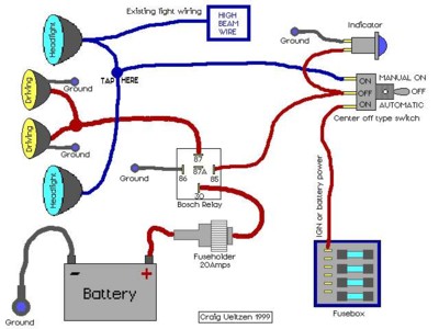
How do I wire driving lights?
What is an Auto Electrician?
An Auto Electrician is a person who is
professionally trained technician in repairs to all electrical
operating components on a motorizes vehicle. E.g. Starting system,
charging system, lights, wiring, etc.
What is the wiring code for a seven /
five pin plug socket for a caravan / trailer?
Five pin round plug & socket wiring
code:
on the bottom of all sockets there are
numbers in which the socket can be wired.
| 2. Left hand Flasher Lamps. |
Yellow |
| 3. Earth. |
White |
| 5. Right Hand Flasher Lamps. |
Green |
| 6. Stop Lamps. |
Red |
| 7. Tail Lamps. |
Brown |
Seven pin round plug & socket wiring code:
| 1. Left Hand Flasher Lamps. |
Yellow |
| 2. Reversing Lamps / Aux. |
Black |
| 3. Earth. |
White |
| 4. Right Hand Flasher Lamps. |
Green |
| 5. Service Brake ( Caravan /
Trailer ) |
Blue |
| 6. Brake Lamps. |
Red |
| 7. Tails Lamps. |
Brown |
Six pin plug & socket wiring code:
| 1.Tail Lamps |
Brown |
| 2. Left Hand Flasher Lamps. |
Yellow |
| 3. Right Hand Flasher lamps. |
Green |
| 4. Stop Lamps. |
Red |
| 5. Service brakes. |
Blue |
| 6. Earth. |
White |
Seven pin heavy duty 70 amp round plug & socket wiring code:
| 1. Earth. |
White |
| 2. Reversing Lamps. |
Black |
| 3. Left Hand Flasher Lamps. |
Yellow |
| 4. Stop Lamps. |
Red |
| 5. Right Hand Flasher Lamps. |
Green |
| 6. Tail Lamps. |
Brown |
| 7. Service Brakes |
Blue |
Twelve pin flat plug & socket wiring code:
| 1. Left Hand flasher Lamps.. |
Yellow |
| 2.Reversing Lamps. |
Black |
| 3. Earth. |
White |
| 4. Right Hand flasher lamps. |
Green |
| 5. Service brakes. |
Blue |
| 6. Stop Lamps. |
Red |
| 7. tail Lamps. |
Brown |
| 8. Battery Supply. |
Orange |
| 9. Auxiliaries. |
Pink |
| 10. Earth. |
White |
| 11. Rear fog lamps. |
Grey |
| 12. Auxiliaries. |
Violet |
Seven pin flat plug & socket wiring code:
| 1. Left Hand Flasher lamps. |
Yellow |
| 2. Reversing Lamps. |
Black |
| 3. Earth. |
White |
| 4. Right hand Flasher lamps. |
Green |
| 5. Service Brakes. |
Blue |
| 6. Stop Lamps. |
Red |
| 7. Tail lamps. |
Brown |
What is the wiring code for a standard relay?
Relay wiring code:
| 30 |
Positive battery supply |
| 86 |
From switch source |
| 85 |
Earth |
| 87 |
To load e.g. Driving lights |
| 87a |
To load when relay is not activate |
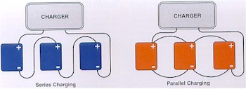
Charging your battery
Before attempting to charge a battery, be aware of all
the safety precautions you should observe during the charging
operation.
- Always turn the charger off before attaching,
rocking, or removing the terminal clamps.
- Keep open flames and sparks away from the
battery.
- Keep vent caps in place.
- Charge in well ventilated area.
- Follow the battery charger manufacturer's
instructions.
Specific charging rates or times are difficult to
detail due to a number of other features such as:
- The electrical capacity of the battery.
- Temperature of the electrolyte.
- Battery state of charge at the start of the
charging period.
- Battery age and condition.
Battery Charging Guide
Rated
Battery Capacit
(Reserve Minutes)y |
Slow
Charge |
Fast
Charge |
| 80 Mins or Less |
15 hrs. @ 3 Amps |
2.5 hrs. @ 20 Amps
1.5 hrs @ 30 Amps |
| Above 80 to 125 Mins |
21 hrs. @ 4 Amps |
3.75 hrs. @ 20 Amps
1.5 hrs @ 50 Amps |
| Above 125 to 170 Mins |
22 hrs. @ 5 Amps |
5 hrs. @ 20 Amps
2 hrs @ 50 Amps |
| Above 170 to 250 Mins |
23 hrs. @ 6 Amps |
7.5 hrs. @ 20 Amps
3 hrs @ 50 Amps |
| Above 250 Mins |
24 hrs. @ 10 Amps |
6 hrs. @ 40 Amps
4 hrs @ 60 Amps |
6-Volt and 12-Volt batteries recommended charging rate
and time from a Fully Discharged Condition (i.e. Flat, Discharged).
Fast Recharging is not Recommended.
Check the batteries specifications for the Reserve
minutes.
"Calcium" Batteriers - What are they?
The Calcium in "calcium batteries" refers to the lead
alloy used in the production of the grids for plate making. The
alloy is typically still 99% lead with alloying metals.
Lead acid starting batteries can be produced from a number of
different lead grid alloys. Pure lead is hardened by the
addition of alloying metals, e.g..
Low Antimony Alloy = 1.75% antimony (+ tin, arsenic)
Calcium Alloy = 0.1% calcium (+ tin, aluminum)
Silver Alloy = 0.06% Silver with Calcium (+ tin, aluminum)
Grids can be produced by various methods such as:
- Gravity cast
- Expanded, from cast or wrought lead alloy strips
- Continuous cast
These types of batteries are commonly known according to their grid
construction as:
Grid Type
|
Construction
|
|
Low Antimonial |
low antimonial alloy positive and negative
grids |
|
Hybrid |
low antimonial alloy positive and calcium
alloy negative grids |
|
Calcium / Calcium |
calcium alloy positive and negative grids |
Calcium lead alloys are not new, calcium having been considered as
an alternate hardener for lead alloy in the 1930's.
Calcium alloy grids are used primarily
- because of their low water loss and low
self discharge characteristics, and
- the rapid solidification point of the alloy allows the operation
of continuous grid making process.
Calcium lead alloy grids were found to be prone to grid growth and
cracking, leading to premature battery failure. This has been
controlled by modifying the alloy and roll hardening the positive
grid, or the use of calcium/silver alloys.
Maintenance Free Batteries- truly maintenance free?
By definition, a Maintenance Free battery is one which, during its
operating life and under normal operating conditions, will not require
water addition (maintenance).
All three grid types listed above can be used to produce
'maintenance free batteries'. Regardless of the grid alloy
combinations, all batteries will gas and lose water from the
electrolyte.
The hydrogen over-voltage increases from antimonial to hybrid, and
from hybrid to calcium / calcium construction. 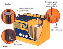 This
means that at a given rate of overcharge at the same temperature, an
antimonial battery will consume more water than a hybrid, and a hybrid
will consumer more water than a calcium / calcium build. This
means that at a given rate of overcharge at the same temperature, an
antimonial battery will consume more water than a hybrid, and a hybrid
will consumer more water than a calcium / calcium build.
A healthy electrolyte reservoir (volume of electrolyte above the
plates) in the battery is critical for maintenance free performance,
regardless of the grid combination used. Sealed cover type MF
batteries (eg. AC Delco) will still gas during overcharging and lose
water from the electrolyte reservoir. The ability to still
service an MF battery subjected to adverse conditions will extend
operating life.
Calcium Alloy Batteries - the Pros and Cons
Some typical calcium alloy battery characteristics, when compared
with low antimonial batteries are:
- Lower self discharge rate, which increases shelf life and
extends the charge period during shipping of vehicles. At
the same temperature, shelf life periods are typically 2 months
for low antimonial, 4 months for hybrid and 8 months for calcium /
calcium.
- Lower water loss (gassing rate) under
overcharging conditions. Test by VW-Europe showed the
following comparative water loss rates:
| 1.7%
antimony |
5
to 7 grams per amphour |
|
Hybrid |
3 to 5 grams per
amphour |
| Calcium /
Calcium |
1.5 to 2.5 grams
per amphour |
- Lower internal resistance which provides a small increase in CCA
performance.
- Higher charge rate acceptance.
- Can result in reduced positive grid life under cycling
conditions, and at elevated operating temperatures. Positive
plate failure can be through grid corrosion or loss of positive
active material.
- 'Barrier Layer Sulphation' problems occur if fully discharged
(flat). The battery can then be difficult to recharge,
requiring a higher voltage charge. Battery life may be
reduced as a result of 'barrier layer sulphation' as full capacity
may not be regained.
- The key to the life and performance of
calcium / calcium MF batteries is in the tight control of the
manufacturing process and positive plate grid alloy specifications.
- OE manufacturers fitting calcium / calcium
batteries look for benefits in a longer 'stand' life (lower self
discharge). This helps increase the probability of the
vehicle starting after overseas shipment. Lower self
discharge can help to offset standing (parasitic) electrical loads
of, typically, 10 to 30 milliamps.
Motor vehicle Charging system:
Voltage Control / set point
- While calcium alloy batteries can accept higher recharge
voltages, the nominal charging voltage in modern cars is 14.2
volts. (Technically, to charge an antimonial battery, the
effective charge voltage is 14.15 volts at 20?C,
and 13.75 volts at 40?C).
- There is a trend developing, to reduce rather than increase
voltage set points. (Many truck settings are now 14.2 volts for
short distance vehicles, and 13.8 volts for long haul vehicles).
( back to top of page
)
|